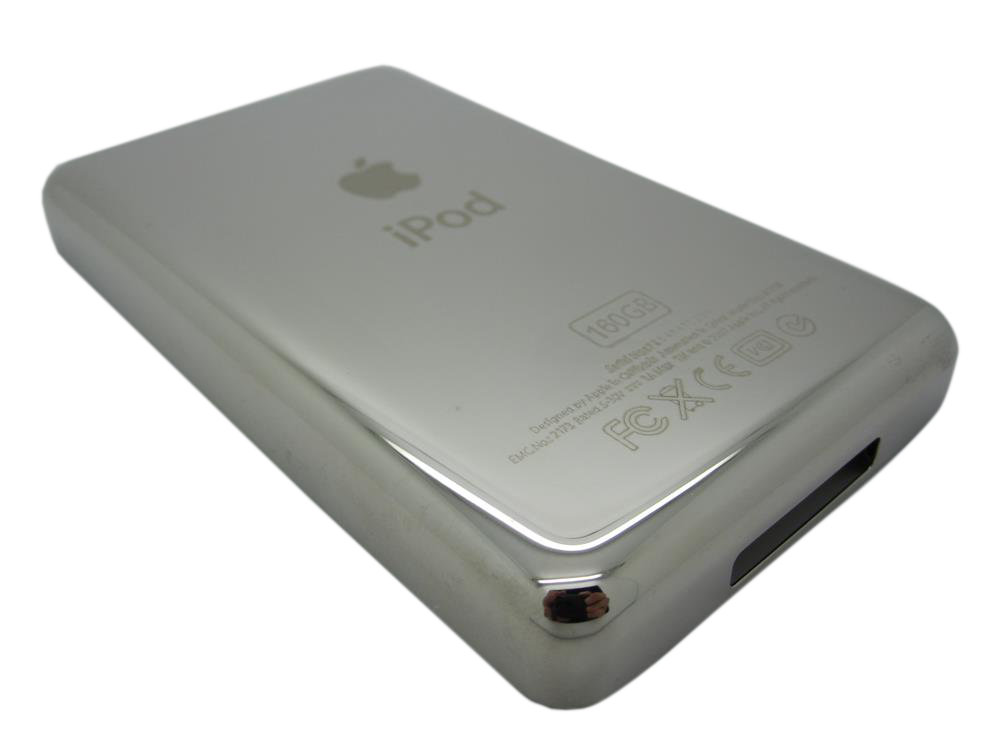
Replacement housing or trim part for iPod Classic 7G. Use it to restore fit, finish, color, case alignment, or visible damage rather than to fix an internal electronics fault.
Product Overview
Choose this backplate listing to restore the visible fit, finish, or mounting hardware on the iPod Classic 7th Generation.
Use the Compatible Variants table below to confirm capacity, color, case, or order-number fitment.
This is a fit-and-finish part, so choose it by physical damage, color, case thickness, and missing hardware rather than by an electrical symptom.
This can also be a customization choice. Non-OEM back panels may be offered in custom finishes or with blank/custom storage-capacity engraving, which is useful when a flash-mod capacity no longer matches the original rear-case engraving. Choose finish and engraving after confirming fitment.
What Is Included
Condition: New replacement part. Quantity and exclusions: The listed part, set, pair, or configuration above is supplied with exactly one plastic pry tool. No other parts, tools, adhesives, or materials are included unless they are explicitly listed above.
In plain words: the rear panel arrives bare. The headphone and Hold assembly screws to the rear panel on this model, so it comes off your old panel and goes on to this one — check its two screws and its ribbon while the case is open, and see the headphone jack page if the assembly itself is damaged. No screws, no adhesive and no screwdriver are supplied; you supply the Phillips #00 driver.
Quick Buying Check
Buy this when
- Use this Replacement Backplate (160GB — Silver) check for damaged, missing, mismatched, or physically worn; diagnose internal symptoms separately.
- The original rear panel is scratched, dented, bent, broken, missing, loose, or cosmetically worn.
- The model, rear engraving, capacity, and order number match this listing.
Diagnose first when
- Confirm the capacity match before ordering: 160GB.
- Confirm the case thickness before ordering: thin. Apple's figures for the late-2009 thin Classic are 0.41 inch / 10.5 mm deep and 4.9 ounces / 140 g. Treat those as supporting checks rather than proof — a replaced case, drive or battery changes the weight — so measure the depth and go by the order number.
- Confirm the color variant before ordering: Silver.
Do not buy for
- Do not use this part for: Other rear-capacity engraving routes when you want a stock-looking 160GB backplate.
- This is a visible exterior customization part; it is not proof of a failed electronic component.
Cracks or broken plastic
Cracked, brittle, or broken exterior pieces are good reasons to replace the cosmetic or structural part.
Specifications & Fitment
Part Details
| Detail | Value |
|---|---|
| Model Number | A1238 |
| EMC | EMC 2173 |
| Condition | New replacement backplate |
Compatible Variants
| Order Number | Capacity | Case | Compatible | Notes |
|---|---|---|---|---|
| MB147LL/A | 80GB | thin | Yes— fits (engraving cosmetic) | Owner-verified fit: same-depth thin backplates interchange; the rear engraving reads 160GB while the 80GB unit's original reads 80GB (cosmetic only). Unit sold under the iPod Classic 6th Generation pages. |
| MB565LL/A | 120GB | thin | Yes— fits (engraving cosmetic) | Owner-verified fit: same-depth thin backplates interchange; the rear engraving reads 160GB while the 120GB unit's original reads 120GB (cosmetic only). Unit sold under the iPod Classic 6th Generation pages. |
| MC297LL/A | 160GB | thin | Yes— compatible | Color swap — physically fits, different color from original |
| MC293LL/A | 160GB | thin | Yes— stock match | — |
| MB150LL/A | 160GB | thick | No— thick-case 2007 160GB part set | The 2007 thick 160GB rear case, battery, hard drive, HDD cable, bumpers and headphone jack are not compatible with thin models; sold under the iPod Classic 6th Generation pages |
| MB145LL/A | 160GB | thick | No— thick-case 2007 160GB part set | The 2007 thick 160GB rear case, battery, hard drive, HDD cable, bumpers and headphone jack are not compatible with thin models; sold under the iPod Classic 6th Generation pages |
Cosmetic Failure Signs — When to Replace
This rear panel is a cosmetic part — it does not change how the iPod plays, charges, or syncs. Replace it when the damage is physical:
| Symptom | What it means & what to check |
|---|---|
| Dents and bent corners | Drop damage that keeps the polished back from sitting flush at the case seam. |
| Deep scratches and gouges | Hairline swirls are normal wear on a polished back; replace when scratches are deep enough to catch a fingernail. |
| Worn or unwanted engraving | A previous owner's engraving, or capacity text that no longer matches the build, reads wrong on an otherwise clean unit. |
| Loose fit after an earlier opening | A bent rim or clip from previous service keeps the seam from closing cleanly. |
| A case that will not close flat, or a lifted screen | Check the battery before you buy a new shell. On this model the pack lies behind the display, so a swelling cell lifts or bows the screen, spreads a dark blot across it, and stops the case sitting flat — a new panel does not fix that. Stop charging, never press a lifted screen back down, and start on the battery page. |
Not every buyer here is fixing damage: matching the original silver finish after another repair, restoring a gift or keepsake iPod to clean condition, and finishing a refreshed shell while the case is already open are just as common.
Do Not Buy This Rear Panel Yet If...
| Situation | Start here instead |
|---|---|
| Your Classic is an 80GB or 120GB thin 6G and you want matching engraving | Use the 6G backplate listing for that capacity; this panel fits the thin case but is engraved 160GB. |
| Liquid, corrosion, or board-side damage changes the diagnosis | Use this rear panel only when the visible fit, finish, or physical damage matches. |
| You see a folder icon, clicking noise, or restore failure | A folder with an exclamation mark means the iPod cannot find its storage — the drive, its ribbon cable, or the software on it. Check the drive or flash media, storage cable, adapter seating, formatting, and restore path before replacing any part. |
| Variant or capacity does not match this listing | Confirm exact model, capacity, case, and variant fit before ordering. |
| A symptom points to a different part | Start with battery for power/runtime symptoms; hard-drive cable for folder, clicking, or restore symptoms; LCD screen for display-only symptoms; headphone jack for audio or Hold-switch symptoms; click wheel (black) or (white) for click-wheel or control symptoms; logic board for board-side damage or multi-system symptoms before buying this part. |
Install Overview
Before You Start
Set Hold to locked (orange bar visible) before opening. Confirm the model and variant before opening the iPod.
Treat case opening as the highest handling risk. Work around the seams gently and stop if the shell, clips, or internal stack resist.
Do not pull the halves apart or side-load board sockets. Reseat nearby ribbons and connectors before blaming a replacement rear panel.
Confirm thickness, color, screw points, and nearby hardware alignment before pressing the case fully closed.
Disassembly Guide
Disassembly guide summary: iPod Classic Rear Panel Replacement.
Show all 32 installation steps
For safety, completely discharge the iPod before disassembly. This reduces dangerous thermal-event risk if the battery is accidentally damaged during repair. If the battery is swollen, take appropriate precautions. This iPod case is unusually hard to open without damaging major components. Its metal faceplate, metal backing, and thirteen metal clips make disassembly especially demanding. Caution: this opening method can significantly damage the iPod beyond its current condition. Keep a few extra plastic opening tools nearby, since they are easy to ruin while opening the case. Confirm that the hold switch is locked before you open the iPod.
Opening this iPod is challenging, so do not get discouraged if it takes a few tries. Watch the plastic opening tool tip angle as you insert it into the iPod; keep it as vertical as possible while still clearing the rear panel edge. Guide a plastic opening tool into the seam between the front and rear of the iPod.
Slide a second plastic opening tool into the seam between the iPod front and rear, keeping the two tools at least 1.5 inches apart.
Working at an angle, carefully slide a putty knife about 1/8 inch into the gap between the two opening tools. You will find thin metal rails running along the inside of the back panel, so work very carefully when inserting the putty knife. After the putty knife clears the rear panel lip, rotate it vertical and carefully but firmly work it straight down through the opening tool gap.
Press on the rear panel behind the putty knife with your fingers to reduce bending. Slowly flex the putty knife so most metal tabs along this side of the iPod release. The idea is to control how the rear panel bends instead of trying to prevent all bending. Any side bend should draw the rear panel lip away from the iPod, not push outward on the curved surface. This also releases as many side clips as possible.
Take the putty knife out, then place it closer to the iPod corner and use the same gentle wiggle method. If possible, do not bend the rear panel corner.
Between the lock slider and headphone jack, guide a plastic opening tool into the seam between the front and rear of the iPod. It may be easier to flex the putty knife downward carefully to create more room for the opening tool. Be careful not to bend the rear panel corner.
Near the display center, carefully slide a metal spudger into the gap made by the plastic opening tool. A visible bump can form here in the rear panel and is hard to repair. When levering the tab free, pivot the metal spudger on the rear panel edge instead of bending the rear panel outward. With the metal spudger, release the single clip at the iPod top edge.
Near the other top corner, insert an opening tool into the gap between the front and rear of the iPod
On the other side, insert an opening tool into the gap between the front and rear of the iPod. It may help to angle the opening tool stuck in the top corner to create enough of a gap.
Take out the plastic opening tool from the top corner and slide it into the seam between the front and rear of the device, leaving at least 1.5 inches of space between the 2 tools (as done on the other side).
Working at an angle, carefully slide a putty knife about 1/8 inch into the gap between the two opening tools. Again, you will find thin metal rails running along the inside of the back panel, so work very carefully when inserting the putty knife. After the putty knife passes the rear panel lip, turn it vertical and carefully but firmly work it straight down through the gap between the plastic opening tools. Press on the rear panel behind the putty knife with your fingers to reduce bending. Flex the putty knife just enough to make sure most metal tabs along this side of the iPod release.
The metal clips near the corners grip the front panel tightly. Release these clips before opening the iPod. Carefully slide a metal spudger into the area beside the stubborn metal clip.
Gently work the metal spudger downward until it is fully seated in the rear panel.
Gently start releasing the clip from the front panel. A visible bump can form here in the rear panel and is hard to repair. When levering the tab free, pivot the metal spudger on the rear panel edge instead of bending the rear panel outward.
Use the metal spudger to apply upward pressure under the front panel until the metal clip releases.
You will find two ribbon cables connecting the rear panel to the remaining iPod assembly. In the following step, take care not to damage these ribbon cables. In this step, grasp the front-panel assembly with one hand and the back panel with the other. Pause for a moment before continuing. Very gently release the remaining rear-panel clips by pulling the tops of the front and rear panels apart, using the iPod bottom as a hinge. Take great care not to damage the ribbon cables joining the two halves.
The battery flex cable lock tab is very delicate. Pulling too far, or pulling on the connector's white portion, can tear it from the main board. If that happens, battery connector repair becomes very difficult. With angled tweezers or an opening tool, raise the brown lock latch straight up by 1 mm. Confirm you draw from both sides of the latch. Take care not to pull on the white portions extending to the connector's outer edges. Move the brown lock tab straight upward. The connector is fragile and can break if it shifts to the side. Grasp the flex cable with your fingers or tweezers and draw it straight up to detach it. If using tweezers, avoid grasping the cable too close to the socket or the cable contacts may short.
Set the rear panel beside the iPod, taking care not to strain the orange headphone jack cable.
Raise the hard drive with one hand to expose the headphone jack ribbon underneath. With a spudger, flip up the plastic tab securing the headphone jack ribbon in place. The tab can rotate up 90 degrees, releasing the ribbon cable. Move the orange headphone jack ribbon out of its connector. The rear panel is now released from the iPod.
After opening, check the rear-panel clips. If any clip bent upward, press it back down gently so the rear case can close cleanly.
Use the broad, flat face of the metal spudger to press the clip downward. Work carefully so the thin metal rail does not tear away from the rear panel. Flat pin-nosed pliers can reduce slipping and headphone jack damage risk. While shaping these clips, take care not to damage any headphone jack parts.
Set the rear panel on its side on a clean, hard surface. Carefully but firmly press it downward, rolling the full lip edge back into place. You may need to repeat this several times to straighten the sides well. Slightly overcorrecting the case edges inward is better than leaving them too far out, because reseating the front panel will bend the rear panel back into alignment. Once the rear panel is restored to good condition, continue with the iPod repair.
The battery sticks to the rear panel adhesive. As you remove it, take care not to tear the orange ribbons for the headphone jack or hold button. With a spudger, raise the battery and the attached orange cable out of the device. If you have a 160GB iPod, the battery will be thicker than thinner battery variants. If the battery is hard to remove, warm the OUTSIDE of the rear panel with a hair dryer on its low setting for 20–30 seconds — never a heat gun, and never heat aimed at the cell. If the pack is swollen, discoloured, or warm to the touch, stop: do not pry it and do not heat it. A punctured or overheated cell can vent or ignite.
Hold the orange ribbon cables in place with one hand, then peel up the black tape securing those cables to the rear panel with your other hand.
Take out the two black Phillips screws securing the headphone jack to the back panel. These screws are small; make sure a size 00 screwdriver is on hand.
Take out these two screws: Fastener detail: one black Phillips screw holding the hold switch near the corner of the device. Fastener detail: one silver Phillips screw securing the other edge of the hold switch.
Raise the hold switch free from its housing on the rear panel. Do not remove the hold switch completely yet because it shares the headphone jack cable.
Move the headphone jack out of its housing on the rear panel. Raise the headphone jack and hold switch assembly out of the iPod.
If you're just trying to take out the rear panel, you can skip Steps 30 and 31. If the replacement headphone jack includes the white plastic hold switch, reinstall the replacement headphone jack. When replacing the hold switch assembly, align the locating pin near the silver screw hole first; the rest then settles into place. After the screws are in, remember to peel the backing tape from the contact pad along the jack. If the replacement part lacks the plastic hold switch, use the next steps to transfer the switch to the new headphone jack. Take out the single Phillips screw nearest to the hold switch. Raise the plastic part of the Hold switch away from the orange ribbon cable. During switch reassembly, confirm that the black notch lines up with the gray slider.
With the small plastic opening tool, carefully peel up the orange ribbon cable and attached black Hold switch from the metal backing. When attaching the replacement Hold switch, align the two small rear posts on the switch with the two holes in the metal backing.
Only the rear panel remains.
Product-specific placement, reassembly, and check
- Prepare and access. Confirm the exact model and listing fit first. Use the existing steps as a disassembly guide, gather the specified tools, disconnect power where applicable, and keep screws and cable positions organized.
- Place Replacement Backplate (160GB — Silver). Transfer only the components required by the existing access steps, then align the listed cosmetic or structural part with its clips, openings, and edges.
- Reassemble without force. Reverse only the access steps needed for this repair, keep cables clear of case edges and screw posts, and close clips in stages.
- Validate before final closure. Before final closure, confirm an even fit and verify that buttons, switches, ports, display, and wheel movement remain unobstructed.
Stop condition: Stop if a connector, latch, screw, clip, housing edge, or the replacement part resists normal alignment. Recheck model fit, orientation, cable routing, and trapped hardware instead of forcing it.
After This Repair
| Check | What to do |
|---|---|
| Check rear fit | Confirm the rear housing sits flush, matches the intended capacity and case depth, and does not pinch transferred hardware. |
| Watch nearby parts | Reopen if the case bows, rattles, or puts pressure on the battery, storage, display, or control stack. |
Frequently Asked Questions
How do I know this backplate is the right one?
Match capacity 160GB and color Silver, the A1238 model family, and the order number in the fitment table before ordering.
Will this fix charging, audio, storage, or screen problems?
No. A backplate is passive rear housing. Use it for dented, scratched, bent, missing, or custom rear-case work, not as an electronics diagnosis.
Is this an iPod Classic?
Apple sold this model as iPod classic (Late 2009). '7th Generation' is common repair-market shorthand for the thin 160GB A1238 model, not an official Apple product name.
Should I choose by capacity engraving?
Yes. Use the rear capacity engraving and 7G A1238 fitment table first so the replacement rear panel matches the iPod being repaired.
How do I confirm this is the right exterior part?
Match the exact iPod Classic 7th Generation model, visible part shape, color or finish goal, and any capacity or case-depth note before ordering Replacement Backplate (160GB — Silver).
Worth Knowing
- Some aftermarket backplates have poor tolerances: screw holes may not line up with the inner frame and the jack or frame screws may not seat. Check screw alignment before pressing the case closed.
- The rear panel is chromed stainless steel and the front panel is anodized aluminum, which is why the two halves scratch, mark and polish differently.
Why people land on this part
Also searched as: Won't Restore, iPod classic 7th generation 160GB silver backplate replacement, iPod classic 7th Generation 160GB silver rear case, iPod classic 7th Generation 160GB silver back cover, iPod classic 7th Generation 160GB silver rear housing, iPod classic 7th generation back plate, iPod classic seventh generation 160GB silver backplate repair service, iPod classic seventh generation 160GB silver backplate replacement guide, iPod classic seventh generation replacement 160GB silver backplate kit, iPod classic 7th generation rear panel, Physical Damage.