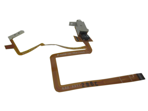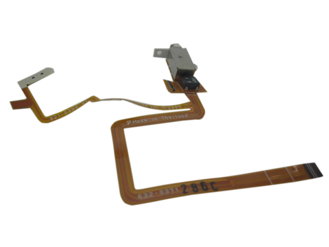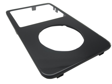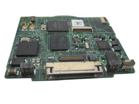
Board-side connector damage
Corrosion, torn sockets, or damaged board traces are stronger board signals than a symptom name alone.
Free US shipping on orders of $200 or more
Your iPod:
Get started
Order a repair (or free diagnostic if you're unsure)
Print the work order from your confirmation email
Package up your iPod and ship it to us, or buy our protective box and prepaid shipping label
About the diagnostic: When your iPod arrives, we test it, perform analysis, and send you a free repair quote. If you don't like our price, we will ship your iPod back at our expense.

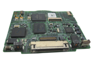
Representative photo. You receive the part named above.
Used (Apple Original) · Model A1136
$125.90
Sold out
We are not selling this part at the moment.
Part details
Overview
Replacement 30GB 5.5G Enhanced logic board for iPod Video. Confirm the removed board marking and whether the SKU includes only the bare board or any attached frame/cables before ordering.
Fitment snapshot
Confirm model, generation, part number, and fitment details before ordering.
This logic board listing covers Factory Original Logic Board (30GB 5.5G Enhanced) and its own connector path on the iPod 5th Generation (Video).
Use the Compatible Variants table below to confirm capacity, color, case, or order-number fitment.
Use the fitment and inspection checks below before ordering, especially when the same model family has thin/thick case or connector variants.
If known-good cable, power, storage/ribbon, connection, and restore or Disk Mode checks still fail, the logic board remains a suspect, especially when corrosion or board-side connector damage is visible.
This part comes in multiple variants. Confirm your iPod's capacity, case depth, and order number before ordering.
The 32 MB option of the 820-1975-A board, for 2006 Enhanced 30GB A1136 builds.
Condition: Used factory-original part. Quantity and exclusions: The listed part, set, pair, or configuration above is supplied with exactly one plastic pry tool. No other parts, tools, adhesives, or materials are included unless they are explicitly listed above.
Fit and specs
Do this before you choose, because the outside of the iPod cannot answer it. Every iPod Video reads A1136 on the back — the 2005 originals and the 2006 Enhanced models alike — so the model number decides nothing here. The board number and the memory decide everything.
820-1975-A is the family this listing belongs to, from the 2006 5.5G Enhanced. 820-1763-A is the original 2005 5th generation family and has its own pages. Boards from the two families cross-fit inside the Video range, but they are not the same part and we list them separately.This listing is the 32 MB option of the 820-1975-A board, for the 30GB Enhanced iPod Video. “Enhanced” is Apple's Fifth Generation iPod (Late 2006): the same A1136 body with a brighter display, on-device Search, gapless playback and improved video decoding — which is what tells an Enhanced build apart from a 2005 original before you read the board. The 64 MB option of the same board is the 80GB Enhanced page — match the memory your iPod left the factory with unless you deliberately want the other. Owners who have swapped up report the extra memory helps the iPod get at a large library on a big drive rather than improving sound or video; we do not promise a track count for either option, and we confirm the exact board and memory option before it ships.
| Detail | Value |
|---|---|
| Model Number | A1136 |
| EMC | EMC 2065 |
| Condition | Used — factory original Apple part. Normal cosmetic wear expected. |
| Release family | 5.5G Enhanced / 2006 |
| Memory (this listing) | 32 MB |
| Memory as shipped by Apple | 32 MB with the 30GB builds, 64 MB with the 60GB and 80GB builds |
| Known board family |
820-1975-A family; confirm marking before ordering |
| Order Number | Capacity | Color | Case | Compatible | Notes |
|---|---|---|---|---|---|
| MA146LL/A | 30GB | Black | thin (0.43 in) | Yes— compatible (cross-compatible board) | Owner-verified: 5G/5.5G logic boards are cross-compatible — 5G 30GB units accept the 5.5G board |
| MA446LL/A | 30GB | Black | thin (0.43 in) | Yes— stock match | — |
| MA664LL/A | 30GB | Black/Red | thin (0.43 in) | Yes— stock match | — |
| MA452LL/A | 30GB | U2 Special | thin (0.43 in) | Yes— compatible (cross-compatible board) | Owner-verified: 5G/5.5G logic boards are cross-compatible — 5G 30GB units accept the 5.5G board |
| MA002LL/A | 30GB | White | thin (0.43 in) | Yes— compatible (cross-compatible board) | Owner-verified: 5G/5.5G logic boards are cross-compatible — 5G 30GB units accept the 5.5G board |
| MA444LL/A | 30GB | White | thin (0.43 in) | Yes— stock match | — |
| MA147LL/A | 60GB | Black | thick | Yes— compatible (cross-compatible board) | Owner-verified: 5G/5.5G logic boards are cross-compatible; this 30GB board carries 32MB RAM where the 60/80GB originals shipped 64MB; owners report the smaller memory mainly makes the iPod slower to get at a big library, not worse-sounding |
| MA003LL/A | 60GB | White | thick | Yes— compatible (cross-compatible board) | Owner-verified: 5G/5.5G logic boards are cross-compatible; this 30GB board carries 32MB RAM where the 60/80GB originals shipped 64MB; owners report the smaller memory mainly makes the iPod slower to get at a big library, not worse-sounding |
| MA450LL/A | 80GB | Black | thick | Yes— compatible (cross-compatible board) | Owner-verified: 5G/5.5G logic boards are cross-compatible; this 30GB board carries 32MB RAM where the 60/80GB originals shipped 64MB; owners report the smaller memory mainly makes the iPod slower to get at a big library, not worse-sounding |
| MA448LL/A | 80GB | White | thick | Yes— compatible (cross-compatible board) | Owner-verified: 5G/5.5G logic boards are cross-compatible; this 30GB board carries 32MB RAM where the 60/80GB originals shipped 64MB; owners report the smaller memory mainly makes the iPod slower to get at a big library, not worse-sounding |
Install and repair
Run these checks before replacing the logic board — they confirm the logic board is the right fix and not a nearby fault:
For pre-open diagnosis, unlock Hold and reset if needed — toggle Hold on and off, then hold Menu + Select for 6 to 10 seconds. Before opening, lock the Hold switch so the orange bar is visible, then confirm the model and variant.
Treat case opening as the highest handling risk. Work around the seams gently and stop if the shell, clips, or internal stack resist.
Do not pull the halves apart or side-load board sockets. Reseat nearby ribbons and connectors before blaming a replacement logic board.
Test known-good replaceable assemblies first so the board is not blamed for a battery, storage, cable, control, screen, or audio path.
If the symptom appeared after opening the iPod or replacing a part, inspect and reseat nearby ribbon cables and connectors before assuming the replacement part is bad.
Open ribbon-cable latches only as described; over-lifting or side-loading the latch can damage the connector. Do not fully separate the case halves until the remaining ribbons are released; the back panel can still be connected by ribbon cables.
Disassembly guide summary: iPod 5th Generation (Video) Logic Board Replacement.
Before opening the iPod, confirm that the hold switch is locked. With the iPod screen-side down and facing you, the slider should sit all the way to the right.
Do not get discouraged if the iPod takes several opening attempts; work slowly until the case releases. Release the first bottom retainer clip with the plastic opening tool. Point the tool edge toward the metal rear case to avoid scratching the plastic front.
Use these retaining clip locations: four along each side, one on top, and two along the bottom. This helps avoid frustration and reduces the chance of scratching the plastic cover.
Each side of the iPod has four retaining clips. Use a plastic opening tool to separate the plastic front from the metal rear case. Slide the plastic opening tool into the iPod's left side with the tool edge pointed toward the metal rear case. A small guitar pick can help with opening. Place it in the seam and slide it around the case to release the clips more smoothly. Gently enlarge the existing crevice by wiggling the plastic opening tool and moving it to the left. Keep working this way until the entire side of the iPod is loose. Then slide a plastic opening tool to the right of the Hold button. Work very carefully while inserting the tool because the display is fragile.
Gently glide the plastic opening tool on the top of the display, making sure to release the retaining clips. The other sides of the iPod should now release easily. If they do not, work plastic opening tools along the right side the same way you did on the left side. In this step, separate the front of the device from the back about an inch (or a couple of centimeters). The iPod casing is now open, but do not fully separate the two halves yet. Two ribbon cables still connect the back panel to the remaining iPod assembly.
With angled tweezers or a plastic opening tool, slide the brown connector latch upward where it secures the orange battery ribbon cable. Pull from both sides of the latch. Lift it only about 1-2 mm to release the cable; do not lift farther or remove it, or the white connector may come with it. Do not raise the assembly very far; lifting too high could pull the battery connector out of the logic board. Move the brown connector straight upward. It is fragile and can break if shifted to the side. Hooks at the bottom hold the cable in place. If an arm breaks, reinstalling the battery cable becomes difficult; put the cable in the slot and press the brown holder into place to stop the cable from slipping out. Take the cable out of the connector.
At this stage there should be one orange ribbon cable still attaching the front housing to the back. At this stage you are able to take out and replace the blue rubber bumpers, or keep going with separating the case. You can replace the battery without separating the case, but opening it farther can make the work easier. Doing so requires one extra cable removal and adds some damage risk.
Raise the hard drive so the headphone jack ribbon connector is exposed. If the hard drive bumpers come loose, put them back with the notch seated in its original orientation.
With the plastic opening tool, gently raise the brown tab of the headphone ribbon cable connector. The tab can rotate up 90 degrees, releasing the ribbon cable. With your fingers, draw out the headphone jack ribbon cable.
The front and rear case halves should now be fully separated.
With a small plastic opening tool, release the black hinge clamping the hard drive ribbon cable. Rotate the tab upward 90 degrees toward the logic board to free the ribbon cable. With your forefinger, hold the ribbon cable in place; detach the drive from the ribbon cable. Confirm that the hard drive rubber side bumpers are installed on the drive. Use the side bumper installation guide for placement. If needed, transfer the blue foam padding from the hard drive to the replacement drive.
Take out the 3 black Phillips screws securing the front panel to the metal framework. Turn the iPod laterally 180 degrees and take out the three black Phillips screws that secure the front panel to the metal framework on the opposite side.
You may meet some resistance near the center of the device as you will find a mild adhesive used to help hold the two parts together. Carefully work along the iPod edge to separate the front panel from the metal framework. Lift the full framework away from the front panel; it carries the display, logic board, and click wheel. Confirm the click wheel button is seated before reinstalling the framework in the front panel.
The front panel should now be released from the remaining iPod assembly.
In this step, rotate the device so the black plastic tab is more accessible to you. Use a small plastic opening tool or fingernail to lift the black plastic tab that secures the display ribbon. The tab rotates upward 90 degrees toward the display and releases the ribbon cable. Use your finger to prevent the cable from lifting upwards. Rock the display loose from the frame, and next, draw it gently outwards to release the display's ribbon cable. You may have to raise the cable away from the 2 white pegs that poke through it near the side of the frame.
The display should now be released from the remaining iPod assembly. During reassembly, it is usually easier to seat the screen between the front panel and framework before connecting the cable. A new screen cable can be stiff enough to loosen the screen while the cable is being reconnected.
In this step, peel up the black tape holding the silver ground strap to the metal framework. The ground strap is very fragile, so make sure it does not break.
Turn the iPod over, then peel up the orange click wheel ground tab from the metal framework. Detach the thin ground tab only; do not detach the wider click wheel ribbon. Carefully press the logic board away from the metal framework, using the squares as push points. Mild adhesive secures the board to the framework, so avoid bending it by pushing too hard in one spot. The framework should now be free from the remaining iPod assembly.
With a small plastic opening tool, flip up the black plastic tab securing the orange click wheel ribbon in place. The black tab can rotate up 90 degrees, releasing the ribbon cable. With a small plastic opening tool, loosen the click wheel cable from the logic board. Take care not to over-bend the cable, since its electronics can be damaged. Detach the click wheel cable from its connector, and raise the entire click wheel assembly away from the logic board. The click wheel should now be separate from the remaining iPod assembly.
With a small plastic opening tool, flip up the brown plastic tab securing the orange hard drive ribbon in place. The brown tab can rotate up 90 degrees, releasing the ribbon cable. Move the orange hard drive ribbon cable straight out of its connector. If adhesive holds the cable to the logic board, carefully pull up on the cable to loosen it. The logic board is the remaining assembly.
Stop condition: Stop if a connector, latch, screw, clip, housing edge, or the replacement part resists normal alignment. Recheck model fit, orientation, cable routing, and trapped hardware instead of forcing it.
| Check | What to do |
|---|---|
| Run the full function check | Verify power, USB sync, storage, display, audio, controls, and charging before treating the repair as finished. |
| Still not working? | Go back through the connected battery, storage, display, dock, audio, and control paths one at a time. |
Troubleshooting
Start here before ordering. Work through the checks in order; a symptom alone does not prove this logic board is bad until nearby parts, cables, fitment, or install issues are separated.
| Symptom | What it means & what to check |
|---|---|
| won't turn on, wont turn on wont charge, replaced battery still dead, won't power on and completely dead | Check battery, dock power, storage load, and connector seating before moving to the board. |
| no audio, sad iPod icon, not detected, charges but not detected, won't take a charge, Dropped / Not Working, iPod frozen after a new hard drive | Use this as a board-level clue only after adjacent assemblies and ribbons have been checked. |
| My iPod has no sound through headphones | Compare headphones, dock audio, and the headphone/Hold assembly before treating the logic board as the cause. |
Use these checks to decide whether this logic board is the right part, whether a nearby part should be checked first, or whether the symptom needs more diagnosis.
| Symptom | What it means & what to check |
|---|---|
| Hold, lock, or input state can mimic another failure |
What you may see: People describe controls or device behavior that changes with the Hold switch, lock icon, or input state.
Check first: Move the Hold switch and watch whether the lock indicator changes.
Most likely cause: The symptom may be routed through the Hold/input path rather than the logic board itself.
Look elsewhere when: Check the Hold switch path first when the device appears locked or ignores input.
|
| Logic Board appears unresponsive or intermittent |
What you may see: People describe behavior where the logic board seems dead, intermittent, or only partly responsive.
Check first: Inspect nearby connectors and flex paths if the iPod has been opened.
Most likely cause: The logic board can be involved, but connector seating, adjacent cables, power state, or board-side paths can produce similar symptoms.
|
| Blank, white, black, lined, or backlight display |
What you may see: People describe a blank screen, white or black display, missing backlight, lines, or a display that changes after impact or repair.
Check first: Confirm the iPod still plays, charges, or is recognized so the screen symptom can be separated from a dead device.
Most likely cause: The logic board can be damaged, but display ribbon seating, connector condition, liquid history, or board-side display circuitry may need checking first.
Look elsewhere when: Check ribbon seating, liquid history, and board connector damage before treating the display as a guaranteed fix. Check the screen and display-ribbon path first when the iPod still powers, plays, charges, or syncs. |
| Dock, USB, sync, or charging connection trouble |
What you may see: People describe charging, USB recognition, sync, or dock-connector behavior that is intermittent or missing.
Check first: Try a known-good cable, charger, and computer port before opening the iPod.
Most likely cause: The logic board can be involved, but cable condition, port contamination, battery state, storage behavior, or board damage can create overlapping symptoms.
Look elsewhere when: Check cable, charger, battery, storage restore state, and board condition when the dock path is not clearly isolated.
Cautions: FireWire can charge this model, but sync and restore checks must use USB. |
| Fitment or model-variant mismatch |
What you may see: People ask whether a similar-looking part from another model, capacity, or generation will work.
Check first: Match the exact model, generation, capacity, and case style shown for the product.
Most likely cause: The logic board may differ by model, case style, connector, cable length, bracket, or firmware/storage expectation.
Look elsewhere when: Check fitment before replacing nearby parts or ordering another copy of the same wrong variant. If the clue repeats after the connector and ribbon are seated, continue with board-level diagnosis. Cautions: A1136 is a family clue, not a complete board-fitment answer.
|
| Headphone output compared with dock or line-out audio |
What you may see: Audio behaves differently through headphones and a dock or line-out accessory.
Check first: Test known-good headphones before opening the iPod.
Most likely cause: Headphone jack contacts or headphone/hold assembly.
Look elsewhere when: If both headphone and dock or line-out audio fail, the jack alone is unlikely.
Cautions: Do not treat a broad no-audio symptom as proof that the headphone jack has failed.
|
| Liquid, corrosion, or residue near this part |
What you may see: People describe symptoms after liquid exposure, dirty contacts, corrosion, or residue around internal parts.
Check first: Look for corrosion, residue, lifted contacts, or darkened connector areas.
Most likely cause: Corrosion can affect the logic board, its connector, or a nearby board path, so liquid history is a reason to inspect before assuming one part is bad.
Look elsewhere when: Check the board connector and nearby assemblies first when corrosion is not limited to this part. |
| Logic Board ribbon, connector, or contact path |
What you may see: People describe symptoms that change after opening the iPod, reseating parts, or disturbing nearby flex cables.
Check first: Inspect the relevant ribbon and board connector before replacing the part.
Most likely cause: The logic board may be fine while its ribbon, connector, latch, or contact path is loose, dirty, damaged, or not fully seated.
Look elsewhere when: Check the board-side connector or adjacent cable first when the damage is not on the replaceable assembly. |
| Power, charging, or runtime symptoms |
What you may see: People describe short runtime, charging trouble, sudden shutoff, or an iPod that will not reliably power on. Check first: Test with a known-good charger and cable before opening the iPod.
Most likely cause: The logic board can be the cause, but charging, dock, storage, or board paths can create similar power behavior.
Look elsewhere when: Check charger/cable behavior, dock connector condition, storage startup clues, and board damage when the symptom is not isolated to battery performance.
|
| Storage warning symptoms usually start with drive or cable checks |
What you may see: People may see a sad iPod, red X, folder icon, clicking drive, restore loop, or storage-recognition problem, especially after drive, flash, cable, or board work. A folder with an exclamation mark means the iPod cannot find its storage — the drive, its ribbon cable, or the software on it; a sad-face iPod and a red X are the same message in other styles.
Check first: Reseat the hard-drive or ZIF ribbon at both the logic-board end and the drive or adapter end before considering a board replacement.
Most likely cause: Most storage-warning symptoms start with the hard drive, hard-drive cable or ZIF seating, flash adapter setup, formatting, or battery load before they point to the logic board.
Look elsewhere when: Check the hard drive, hard-drive cable or ZIF ribbon, flash adapter, formatting, and battery spin-up/load before treating sad iPod, red X, folder, clicking, or restore symptoms as a board failure.
|
| Symptoms changed after repair or reassembly |
What you may see: People describe a new problem appearing immediately after battery, storage, display, audio, or control work.
Check first: Reopen only as far as needed to inspect the areas touched during the repair.
Most likely cause: A post-repair symptom can involve the logic board, but disturbed ribbons, latches, grounding, connector seating, or the wrong variant part are common checks before ordering again.
Look elsewhere when: Check the exact connector or assembly disturbed during the repair before treating the new part as failed. If the clue repeats after the connector and ribbon are seated, continue with board-level diagnosis. |
| Audio output: headphone vs dock or line-out |
What you may see: No sound, one-channel audio, static, buzzing, or uneven volume.
Check first: Test known-good headphones and a known-good track.
Most likely cause: Both headphone and dock or line-out share the symptom after known-good output tests, or board-side audio-path damage is found. Look elsewhere when: Check headphones, headphone jack/hold assembly, dock accessory, and ribbon seating before replacing the logic board. Cautions: Pressure-sensitive audio is a what to look for, not a guaranteed board replacement promise.
|
| Symptom remains after basic checks |
What you may see: The iPod still points back to Factory Original Logic Board (30GB 5.5G Enhanced) after cable seating, battery stability, and nearby connector checks. Check first: Retest with known-good cables or adjacent parts where practical before ordering. Check next: A nearby cable, connector, battery, storage device, display path, audio path, or board path can mimic a bad logic board. |
Corrosion, torn sockets, or damaged board traces are stronger board signals than a symptom name alone.
Use this listing for the 30GB 5.5G Enhanced board family after matching the order number and removed board marking.
| Situation | Start here instead |
|---|---|
| A simpler replaceable assembly has not been tested yet | Test the likely battery, storage, screen, audio, cable, or connector path first. |
| The symptom began after service and could be a loose ribbon, latch, or connector | Reopen carefully, reseat the part that was disturbed, and inspect its latch before buying a board. |
| Only one attached part path is failing, such as screen, storage, audio, or controls | Use the matching screen, storage, audio, or control part page before replacing the logic board. |
| Verify the battery, hard-drive cable, storage device, USB cable, and dock path before replacing the logic board | Run those replaceable-part checks first; return to this board only if the same failure remains. |
| Match the removed board marking, order number, capacity/RAM, and case/storage layout; A1136 alone is not enough for board fitment | Use the sibling logic-board listing that matches the removed board marking and order-number family. |
| If only the headphone output is bad and dock audio works, check the headphone/hold assembly before ordering a board | Start with the headphone jack / Hold switch assembly check. |
When an iPod Video (A1136, 5th generation) loses its audio, it is almost always one of two parts — and you can usually tell which one without opening the case. This model is specifically known for a solder fault under the audio chip on the logic board that mimics a broken headphone jack, which is why so many owners replace the jack once or even twice and still have silence. The tell is simple: a bad jack only kills headphone audio, while a board fault kills the headphone jack and the dock line-out together.
Anecdotal owner reports (not a guarantee or authoritative proof): - The most repeated complaint is sound in one ear only with the headphone jack feeling loose. Owners report music through one earbud no matter which headphones they try, sound returning to both ears only with the plug pulled halfway out or angled and held. One owner asked if a loose jack can simply be tightened — it can't; there is nothing adjustable inside the assembly, and once it stops gripping the plug reliably, replacing the jack assembly is the fix. - A three-year-old unit played fine until the sound started dropping out into heavy static — and the owner discovered that squeezing the lower-right corner of the case brought the music back for exactly as long as the pressure was held. The display showed the song still playing the whole time, and the symptom was identical through headphones and through a dock. Several other owners independently reported the same 'pinch the bottom right corner to get sound' behavior. That squeeze is pressing on the audio chip's cracked solder joints. - Two owners found the strangest version of this fault: cold fixes it. One got sound back briefly after a few minutes in the refrigerator, only to lose it again once the iPod warmed up; another reported twenty minutes in the freezer made the iPod work perfectly until it thawed. That behavior fits the audio chip's known cracked-solder fault — temperature shifts the broken joint's contact, so cooling can briefly restore sound. A related report had buzzing audio at power-on that faded to silence as the unit warmed. - Many owners replaced the headphone jack and still had no sound — one had replaced it on two separate 30GB units, another bought a new jack and hold switch together and got nothing. The detail they all eventually noticed: the dock connector was silent too, while the click wheel's clicker still chirped from inside the iPod. That clicker comes from a tiny beeper on the board, not the music path, so hearing clicks proves nothing about the audio circuit — and silence on both outputs means the jack was never the problem. - A buyer of a used 5G found everything working except the music: nothing through the headphones but a faint background hiss at maximum volume. They had already restored it in iTunes, pressed under the click wheel corner, and tried the freezer with no luck — the pattern of a board-level audio failure that has progressed past the stage where pressure can bridge it. Another owner described the same end state as 'no audio, just a little static' that got louder and quieter with the volume setting. - One-ear problems that appear right after a jack replacement usually point at the installation, not the iPod. One owner's dead side actually switched — left-only before the repair, right-only after — which matches a mis-seated ribbon or a defective replacement rather than a deeper fault. Another replaced the jack for a dead left channel and noticed both channels played fine through a dock, narrowing it to the new jack's seating in the board connector or the part itself.
How it usually progresses: - The board-level failure follows a recognizable arc on this model: it usually starts as occasional crackling, static, or dropouts in one or both ears, advances to pure static, then fades to complete silence on both the headphone jack and the dock output. Heat accelerates an episode — owners describe sound dying within minutes as the unit warms — while pressure on the lower-right corner or a stint in the fridge revives it briefly. Once it reaches the silent stage, even the pressure test may no longer bring sound back. - Jack wear has its own slower arc: it begins with one channel cutting in and out when the plug moves, then needing the plug half-seated or angled to get both ears, and ends with a channel fully dead or no sound from the jack at all — while dock audio stays perfectly normal the whole way. That dock check is what separates this track from the board failure at every stage.
What typically causes it: - Cracked solder under the audio chip is this model's signature audio failure. The Wolfson audio chip sits at the lower-right corner of the logic board, and years of warm-up/cool-down cycles plus normal case flex fatigue the tiny solder joints underneath it until a micro-crack opens. The music path then cuts in and out, turns to static, and finally goes silent on both the headphone jack and dock line-out — while the screen, menus, syncing, and the clicker all keep working. Pressing the lower-right case corner squeezes the crack closed, which is why the pressure test is so telling on this iPod. - Two small capacitors in the board's audio path are the other board-level culprit. The audio signal passes from the chip through small surface-mount coupling capacitors — repair communities know them by their board markings, C145 and C146 — and when one fails or shorts, the music disappears even though playback continues on screen. repair guide experts report that a failed one can sometimes be spotted just by looking at the board. From the outside this looks identical to the chip solder fault, but it matters to a board shop: the capacitors get checked before any heat is applied. One caution if you shop for parts yourself: the capacitance value quoted in audiophile modding guides is the aftermarket upgrade value, not the factory one, so a competent shop measures the originals rather than trusting a forum number. - Worn jack contacts cause the one-ear and loose-jack complaints. The contacts inside the 3.5mm jack fatigue and oxidize with years of plug insertions, so one channel loses contact unless the plug is angled, half-inserted, or held. The jack is part of the combined headphone jack and hold switch assembly mounted in the rear panel — nothing on it can be tightened or adjusted, so once jiggling the plug becomes routine, the assembly is the fix. A few owners caught it early: rapidly plugging and unplugging a few times or a puff of electronics cleaner freed a stuck contact and bought time. - The orange ribbon cable is the assembly's weak point — and a common casualty of other repairs. The jack and hold switch connect to the logic board through a thin orange ribbon that cracks where it bends and snaps if mishandled; repair guides specifically warn it breaks easily during battery and rear-panel work. One owner's ribbon tore while prying up a glued-down battery; another accidentally damaged their iPod and found the ribbon snapped right at the angle where it bends — headphone audio gone while dock audio survived. The brown latch that clamps the ribbon to the board is also fragile, and a broken latch means the ribbon can't seat properly — a frequent hidden reason a brand-new jack 'doesn't work.'
Handle it safely: - If you open the iPod to check the jack ribbon, treat the orange ribbon cables and the brown ribbon latch as the most breakable things inside. The latch flips up gently and forcing it snaps it off. Replacement latch terminals are listed for the drive connector and for the headphone and Hold connector on these boards, so match the damage to the part before writing a board off; owners who improvise with tape instead make intermittent audio worse, not better. A careful first repair prevents the second fault. - The do-it-yourself 'reflow' for the audio chip — pressing on the chip with a wooden dowel while heating it with a heat gun — is a real community method with documented successes, but it puts uncontrolled heat on a board full of small components — and the battery is a glued-in lithium pack a few millimeters away: never put heat near this board with the pack still in the case, and quick reflows often fail again once the original stress returns. If the iPod or its library matters to you, a replacement board or professional rework is the durable path; save the heat gun for a board you're prepared to lose.
Owners searching for this describe it as: ipod video no sound, ipod 5th gen one ear only, ipod headphone jack loose, ipod video crackling audio, ipod static in headphones, replaced headphone jack still no sound ipod, ipod no sound but clicker works, ipod sound comes back when squeezing corner, ipod video no audio from dock or headphones, ipod headphones only work half plugged, ipod freezer trick no sound, ipod 5g audio chip.
On the iPod 5th Generation Video, Won't Charge can describe more than one observable problem. These paraphrased owner reports are anecdotal starting points for diagnosis, not proof that any single part failed.
Owners searching for this describe it as: iPod 5th Generation Video Won't Charge, iPod won't charge, replacement battery won't charge.
On the iPod 5th Generation Video, Won't Turn On can describe more than one observable problem.
Owners searching for this describe it as: iPod 5th Generation Video Won't Turn On, iPod won't turn on, iPod has no power.
These are anecdotal owner reports, not guarantees or authoritative proof that a particular part will fix a symptom. Use them as a troubleshooting starting point: confirm the symptom, run the quick checks, then match the fix.
Owners describe it as: the old board carries a silver ground strap the new one lacks and the guides do not say what to do with it; or a visibly blown capacitor raises the question of a component-level fix.
The strap. Find it where the old board meets the metal frame before lifting the board out — replacement boards usually arrive without one, and the repair guide for this board calls the strap very fragile, so work it free slowly. Owner experience on going without disagrees: two documented builds ran fine strapless, while the answer behind this card holds that it is always wiser to apply it to the new one. Transfer it when it comes off cleanly.
Blown components. Identify the part by its board marking and position: measurement and soldering on the revision in front of you, not a value to order from a forum thread. We print no capacitor value for this board, because none of the accepted sources measures one.
Caution. A white screen after a board swap is worth a strap-and-connections check first, and boards differ by capacity and memory — match the removed board's marking and your order number. Reported by 3 owners.
Owners describe it as: the support-site screen on boot after a board or screen transplant; a blank screen after a board swap; a freeze with a brand-new drive; a sad face immediately after a replacement board went in.
Check first. Everything the swap disturbed: release and re-close the brown clamp on the drive ribbon, re-seat the display ribbon and its lock, and confirm the battery flex is home with its clip down. A board swap disturbs the drive cable by definition.
Then restore. Owners who rebuilt these got there by formatting in Disk Mode and restoring afterwards, so expect a restore after a board swap — and a restore erases the iPod, so copy anything that exists only on it first.
What we will not claim. Nothing shows that a board swap by itself preserves or destroys your music, and the idea that the drive is paired to the board is speculation rather than an established mechanism. Reported by 3 owners, plus one sad face straight after a board replacement.
Owners describe it as: the brown locking clip for a flex — headphone, battery or hard-drive cable — snapping off while parts go back on; a connector popping off the board entirely; a drive cable that refuses to stay latched; no sign of life after a multi-part rebuild.
What it is. The ribbons are held by hinged brown clamps on the board; the drive ribbon's is released with the flat of a small opening tool, and it is the one most often broken. A clamp that will not lock leaves the ribbon making partial contact, which reads on the bench as a failed drive, screen or jack.
What fixes it. Replacement latch terminals are listed for the drive connector and for the headphone and Hold connector on these boards, so match the damage to the part before writing a board off. A connector torn away with its pads is soldering work; a board with damaged pads is a board replacement. Do not assume one connector's listing covers another — the display latch is not one of these. Reported by 4 owners.
Owners describe it as: music plays but no computer sees the iPod; it boots to the restore screen now and then; recognition faded as the battery got weak.
Check first. Another cable and another USB port — a repair technician's first move on this family. Clean the 30-pin connector and look for lint and bent or corroded pins. Then reset (Hold off, Menu + Select) and, still connected, hold Center + Play/Pause until the Disk Mode screen: an iPod the computer's own disk tools can see is a software problem rather than a port one.
What fixes it. The 30-pin port is soldered to the logic board, so a damaged port is board-level work, not a trim part. A tired battery is the cheaper suspect when charging works and recognition comes and goes.
Caution. Reading an intermittent restore screen as early drive failure is one owner's interpretation, not a rule. Reported by 4 owners.
Questions
Use these questions to narrow the part path before ordering. They keep each answer focused on a different diagnostic or fitment decision.
Match the board you removed: its marking, your iPod's order number, the memory it carries and the case depth. The model number on the back is not enough for board fitment on its own.
On the physical question, a same-model answer to an owner asking about a 30GB board in a 60GB Video is direct: "yes, it will fit. You can also use a 80GB logic board in your model." One owner also rebuilt a Video with an Enhanced board. What differs is memory — the 30GB boards carry less than the 60/80GB boards — and that governs how large a track database the iPod can hold.
Expect to restore after a board change, and back up first. A board that ran hot with a melting smell needs its battery and connector checked before it is condemned: in the thread behind this question that turned out to be a mis-seated connector. We confirm the exact board and memory option before it ships rather than promising that any board works in any build.
The display ribbon is held by a black plastic tab that flips up on the board-side connector. When that lock breaks, the ribbon can sit in place without making reliable contact, and the iPod runs on happily — storage spinning, wheel clicking — with nothing on screen.
Check the ordinary explanation first: a blank or abnormal display is usually a loose display cable, so re-seat the ribbon square and close whatever lock remains before concluding anything. With the lock gone, owners hold the ribbon down against the connector; that is a workaround rather than a repair, and pressure applied wrongly damages the flex.
The lock belongs to the board's connector, so a broken one is board-level work or a board replacement. In this case the panel itself is rarely at fault — a screen that has never been shown a signal is not a failed screen. Reported by 1 owner.
This non-custom replacement is factory-original Apple hardware in used condition. Custom-color new exterior parts use separate custom-color pages.
If sound returns, clears, or changes when movement or contact pressure changes the symptom, treat that as a board-level audio clue. On the 5G/5.5G Video, that points toward the board-level audio path before another headphone-jack purchase.
If the iPod works while plugged in but dies quickly when unplugged, treat the report as a battery-health and load test first. Compare BATT A2D or measured voltage with behavior during playback, video, restore, and disk spin-up before naming the battery, hard drive, or logic board as the failed part.
Post-opening handoff: If a new symptom appears after opening the case, route by subsystem before adding another repair step: battery or no-power issues to battery/ZIF checks, screen changes to the display lane, hold or headphone behavior to hold/audio lanes, and storage behavior to storage or restore lanes.
If both the headphone jack and dock line-out are silent, distorted, or change when the contact-sensitive area is pressed, do not treat the headphone jack as the only suspect. After known-good output tests, move the diagnosis toward the board-level audio path or logic-board replacement boundary.
Use dock line-out to split the route. If dock output is clean while the headphone jack has one-channel or intermittent audio, inspect the headphone/hold assembly and ZIF ribbon. If dock and headphones share the symptom, continue checking the board-level audio.
Battery ZIF damage, a lifted connector, abnormal USB current, localized heat, fuse failure, dock inductor damage, or charge-IC evidence can justify board-level routing only after battery, cable, dock, and seating checks. Keep LTC4066, PMU, F1 fuse, and inductor work treated cautiously unless a repair-procedure lane explicitly covers it.
A FireWire source charging the iPod does not test the USB path or the whole charge circuit: try a known-good USB cable and a port on the computer itself (not the keyboard's) before deciding which part is at fault. An aged battery can still take wall current while refusing a computer's, so a split like that is a clue, not a verdict.
Split dock-opening damage into three paths: the plastic dock bezel, dirty or bent visible pins, and the soldered 30-pin connector on the logic board. A cracked plastic surround can be a bezel job; a damaged connector body or failed pin path belongs in board-level diagnosis.
If controls change after reassembly, check click-wheel ribbon seating and the ground path before replacing the click wheel or logic board.
A fresh battery is often replaced during the same repair while the iPod is open.
Related: 128GB Flash Mod Kit (flash-storage adapter + 128GB SD Card Included)Flash storage is the common upgrade path while the iPod is already open.
Related: Replacement Hard Drive (30GB)Use a hard drive only when restoring original-style storage; flash adapters are also a valid upgrade path for 5G/5.5G.
Use the checks above to separate this logic board from nearby parts before ordering.
Some buyers search for "motherboard", "dock connector port", "30 pin dock connector", "iPod 5th gen logic board", "It charges but won't sync", or "most common signs of a bad logic board"; confirm the checks above point to this same part before ordering.
Also searched as: iPod video 5th gen factory original logic board (30GB 5.5g enhanced) replacement, iPod 5th generation video logic board, iPod video 30GB motherboard, iPod video 30GB logic board, dead logic board, no power logic board, won't turn on logic board, 5th gen iPod motherboard, A1136 logic board, connector logic, faulty logic board, FireWire still charges, iPod 5.5 gen logic board, iPod 5G logic board, circuit board, won't turn on won't charge, logic board 30GB enhanced replacement, motherboard, completely dead, ipod classic 5th generation logic board, iPod video 5th gen logic board.
Free diagnostic
Mail us your iPod and we will test it and send you a free repair quote. If you don't like our price, we will ship your iPod back at our expense.