Skip to product information
1 of 1

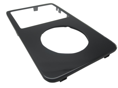
iPod Video 5G — New Custom Thick Backplate

iPod Video 5G — New Custom Thick Backplate

Regular price $52.48 USD
Regular price Sale price $52.48 USD
Sale Sold out
Backplate 60GB / 80GB

Replacement housing or trim part for iPod Video 5G. Use it to restore fit, finish, color, case alignment, or visible damage rather than to fix an internal electronics fault.

Product Overview

Choose this backplate listing to restore the visible fit, finish, or mounting hardware on the iPod 5th Generation (Video).

Use the Compatible Variants table below to confirm capacity, color, case, or order-number fitment.

This is a fit-and-finish part, so choose it by physical damage, color, case thickness, and missing hardware rather than by an electrical symptom.

This can also be a customization choice. Non-OEM back panels may be offered in custom finishes or with blank/custom storage-capacity engraving, which is useful when a flash-mod capacity no longer matches the original rear-case engraving. Choose finish and engraving after confirming thin/thick fitment.

What Is Included

Included

Custom Thick Backplate Free plastic pry opening tool 1 year warranty

Not Included

installation labor unless selected separately, adjacent electronics, battery, storage drive, headphone/hold assembly unless explicitly included.

Quick Buying Check

Buy this when

  • Rear-panel damage, capacity engraving, or case depth: Use this New Custom Thick Backplate check for damaged, missing, mismatched, or physically worn; diagnose internal symptoms separately.
  • The original rear panel is scratched, dented, bent, broken, missing, loose, or cosmetically worn.

Diagnose first when

  • Confirm the color variant before ordering: Black, White.
  • Confirm the capacity match before ordering: 60GB, 80GB.
  • Confirm the case thickness before ordering: thick.

Do not buy for

  • Choose custom options only after confirming model generation and physical fitment. Do not use customization demand as proof of electronics failure.
  • The only problem is an internal electronic symptom with no physical damage to this part.

Cracks or broken plastic

Cracked, brittle, or broken exterior pieces are good reasons to replace the cosmetic or structural part.

What Brings People Here

Custom build

Use a different color or finish for a personalized build after matching the correct generation and fitment.

Specifications & Fitment

Part Details

Detail Value
Model Number A1136
EMC EMC 2065
Condition New custom backplate
Page model Single product page with separately available options
Available color/finish options silver/chrome, black, blue, gold, purple, rainbow
Capacity engraving options 60GB (thick), 80GB (thick), 128GB, 256GB, 512GB, 1TB, Blank / universal
Case fit Thick case

Customization Options

Compatible Variants

Order Number Capacity Color Case Compatible Notes
MA147LL/A 60GB Black thick Yes
MA003LL/A 60GB White thick Yes
MA450LL/A 80GB Black thick Yes
MA448LL/A 80GB White thick Yes
MA146LL/A 30GB Black thin (0.43 in) No— wrong case depth Thick part is not compatible with thin case — risk of LCD damage Use New Custom Thin Backplate instead.
MA446LL/A 30GB Black thin (0.43 in) No— wrong case depth Thick part is not compatible with thin case — risk of LCD damage Use New Custom Thin Backplate instead.
MA452LL/A 30GB U2 Special thin (0.43 in) No— wrong case depth Thick part is not compatible with thin case — risk of LCD damage Use New Custom Thin Backplate instead.
MA664LL/A 30GB U2 Special thin (0.43 in) No— wrong case depth Thick part is not compatible with thin case — risk of LCD damage Use New Custom Thin Backplate instead.
MA002LL/A 30GB White thin (0.43 in) No— wrong case depth Thick part is not compatible with thin case — risk of LCD damage Use New Custom Thin Backplate instead.
MA444LL/A 30GB White thin (0.43 in) No— wrong case depth Thick part is not compatible with thin case — risk of LCD damage Use New Custom Thin Backplate instead.

Cosmetic Failure Signs — When to Replace

This rear panel is a cosmetic part — it does not change how the iPod plays, charges, or syncs. Replace it when the damage is physical:

Dents and bent corners Drop damage that keeps the polished back from sitting flush at the case seam.
Deep scratches and gouges Hairline swirls are normal wear on a polished back; replace when scratches are deep enough to catch a fingernail.
Worn or unwanted engraving A previous owner's engraving, or capacity text that no longer matches the build, reads wrong on an otherwise clean unit.
Loose fit after an earlier opening A bent rim or clip from previous service keeps the seam from closing cleanly.

Not every buyer here is fixing damage: this part is also the route for a color swap or custom build, for restoring a gift or keepsake iPod, and for finishing a refreshed shell while the case is already open.

Do Not Buy This Rear Panel Yet If...

Situation Start here instead
Liquid, corrosion, or board-side damage changes the diagnosis Use this rear panel only when the visible fit, finish, or physical damage matches.
You see a folder icon, clicking noise, or restore failure Confirm restore behavior, storage fit, and setup state before ordering this part.
Variant or capacity does not match this listing Confirm exact model, capacity, case, and variant fit before ordering.
A symptom points to a different part thick.

Install Overview

Before You Start

Confirm the model and reset state

Set Hold to locked (orange bar visible) before opening. Confirm the model and variant before opening the iPod.

Open the case slowly

Treat case opening as the highest handling risk. Work around the seams gently and stop if the shell, clips, or internal stack resist.

Protect nearby connectors

Do not pull the halves apart or side-load board sockets. Reseat nearby ribbons and connectors before blaming a replacement rear panel.

Dry-fit before closing.

Confirm thickness, color, screw points, and nearby hardware alignment before pressing the case fully closed.

Repair Guide

Repair guide summary: iPod 5th Generation (Video) Rear Panel Replacement.

DifficultyModerate
TimeVaries by case condition
Steps18
Common toolsplastic opening tools
Show all 18 installation steps
1

Before opening the iPod, confirm that the hold switch is locked. With the iPod screen-side down and facing you, the slider should sit all the way to the right.

2

Do not get discouraged if the iPod takes several opening attempts; work slowly until the case releases. Release the first bottom retainer clip with the plastic opening tool. Point the tool edge toward the metal rear case to avoid scratching the plastic front.

3

Use these retaining clip locations: four along each side, one on top, and two along the bottom. This helps avoid frustration and reduces the chance of scratching the plastic cover.

4

Each side of the iPod has four retaining clips. Use a plastic opening tool to separate the plastic front from the metal rear case. Slide the plastic opening tool into the iPod's left side with the tool edge pointed toward the metal rear case. A small guitar pick can help with opening. Place it in the seam and slide it around the case to release the clips more smoothly. Gently enlarge the existing crevice by wiggling the plastic opening tool and moving it to the left. Keep working this way until the entire side of the iPod is loose. Then slide a plastic opening tool to the right of the Hold button. Work very carefully while inserting the tool because the display is fragile.

5

Gently glide the plastic opening tool on the top of the display, making sure to release the retaining clips. The other sides of the iPod should now release easily. If they do not, work plastic opening tools along the right side the same way you did on the left side. In this step, separate the front of the device from the back about an inch (or a couple of centimeters). The iPod casing is now open, but do not fully separate the two halves yet. Two ribbon cables still connect the back panel to the remaining iPod assembly.

6

With angled tweezers or a plastic opening tool, slide the brown connector latch upward where it secures the orange battery ribbon cable. Pull from both sides of the latch. Lift it only about 1-2 mm to release the cable; do not lift farther or remove it, or the white connector may come with it. Do not raise the assembly very far; lifting too high could pull the battery connector out of the logic board. Move the brown connector straight upward. It is fragile and can break if shifted to the side. Hooks at the bottom hold the cable in place. If an arm breaks, reinstalling the battery cable becomes difficult; put the cable in the slot and press the brown holder into place to stop the cable from slipping out. Take the cable out of the connector.

7

At this stage there should be one orange ribbon cable still attaching the front housing to the back. At this stage you are able to take out and replace the blue rubber bumpers, or keep going with separating the case. You can replace the battery without separating the case, but opening it farther can make the work easier. Doing so requires one extra cable removal and adds some damage risk.

8

Raise the hard drive so the headphone jack ribbon connector is exposed. If the hard drive bumpers come loose, put them back with the notch seated in its original orientation.

9

With the plastic opening tool, gently raise the brown tab of the headphone ribbon cable connector. The tab can rotate up 90 degrees, releasing the ribbon cable. With your fingers, draw out the headphone jack ribbon cable.

10

The front and rear case halves should now be fully separated.

11

During this step, take care not to damage any headphone or battery ribbon cables. Slide a plastic opening tool between the metal case and the battery. Gently wiggle the tool while pressing it farther between the battery and back case. The battery adhesive should give so the battery can be removed from the rear panel.

12

In this step, be very cautious when performing this step, since the orange ribbon cables can readily be broken. Peel away the tape holding the ribbon cables in place.

13

Take out the two black Phillips screws that are holding the headphone jack to the lower casing.

14

Take out these two screws: Remove the black Phillips screw holding the Hold switch near the corner of the device. Remove the silver Phillips screw securing the other edge of the Hold switch. Reassembly tip: a tiny dab of removable white craft glue on the screwdriver tip can help hold these small screws while you reinstall them.

15

Raise the Hold switch free of its housing on the rear panel. Move the headphone jack out of its housing on the rear panel. Raise the headphone jack and hold switch assembly out of the iPod. If the goal is replacing the back panel, stop here after removing the Hold switch and headphone jack. The next steps only transfer the plastic Hold switch to a replacement headphone jack.

16

If the replacement headphone jack includes the white plastic hold switch, reinstall the headphone jack. If it does not, use the next steps to transfer the plastic hold switch to the new headphone jack. Take out the single Phillips screw closest to the hold switch. Adhesive may hold the screw back in place. Raise the plastic part of the Hold switch away from the orange ribbon cable. During switch reassembly, confirm that the black notch lines up with the gray slider.

17

With the small plastic opening tool, carefully peel up the orange ribbon cable and attached black Hold switch from the metal backing. When attaching the replacement Hold switch, align the two small rear posts on the switch with the two holes in the metal backing.

18

In this step, you are now able to replace the back panel of the iPod.

After This Repair

Check What to do
Check rear fit Confirm the rear housing sits flush, matches the intended capacity and case depth, and does not pinch transferred hardware.
Watch nearby parts Reopen if the case bows, rattles, or puts pressure on the battery, storage, display, or control stack.

Frequently Asked Questions

Is there a separate page for every custom option?

No. This is the single page for the custom option set; choose color/finish and capacity engraving after confirming model fitment.

Is this original Apple OEM?

No. Custom exterior parts are new non-OEM parts. Original factory Apple parts are used OEM and stay on the separate non-custom pages.

Will a custom part fix electronics symptoms?

No. Use this listing for exterior customization, cosmetic damage, or a restomod build. Diagnose controls, charging, storage, audio, and display faults separately.

Worth Knowing

  • This is a visible exterior customization part; it is not proof of a failed electronic component.
  • Custom exterior parts are new non-OEM parts. Factory-original exterior part pages are used factory original Apple unless a listing explicitly says otherwise.
  • Check live product availability before promising a specific color, finish, or engraving option.
  • Owner-verified failure mode: installing a thick-case part in a thin 30GB case compresses the LCD panel against the internals — dark pressure marks or permanent panel damage. Thin and thick batteries, headphone jacks, backplates, and side bumpers are NOT interchangeable between case variants.

Why people land on this part

Also searched as: iPod video 5th gen new custom thick backplate replacement, iPod 5th Generation Video rear case, iPod 5th Generation Video back cover, iPod 5th Generation Video rear housing, A1136 backplate, back housing, chrome backplate iPod video, custom iPod backplate, iPod 5.5 backplate, iPod 5.5g backplate, iPod 5g back plate, iPod 5th generation (video) 30GB backplate replacement, iPod Classic 5th Generation.

  • Genuine Apple Parts
  • One Year Warranty
  • Satisfaction Guaranteed
View full details